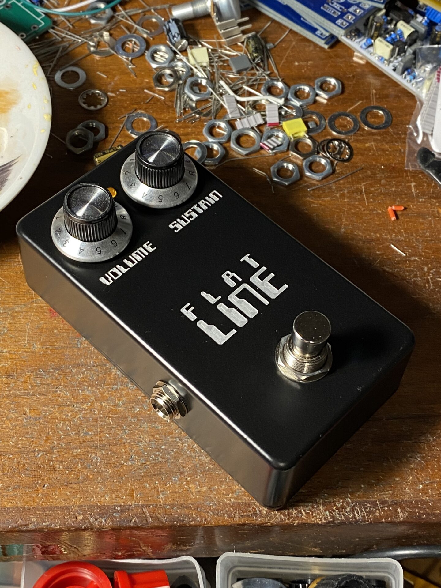
This is a really great little compressor from John Hollis. Follow the guide here to build it yourself. Check out this post to get the background on this project and learn about compressors.
Order PCBs
Schematic

Partslist
| R1 | 330r |
| R2 | 10K |
| R3 | 10K |
| R4 | 47K |
| R5 | 10K |
| R6 | 10M |
| R7 | 10K |
| R8 | 220k |
| R9 | – |
| R10 | 4K7 |
| R11 | 10M |
| D1 | Ge * see notes |
| D2 | Ge * see notes |
| D3 | Ge * see notes |
| D4 | Ge * see notes |
| D5 | LED |
| D6 | 1N5817 |
| C1 | 1n |
| C2 | 100µ |
| C3 | 10µ |
| C4 | 100µ |
| C5 | 10µ |
| LED/LDR | VTL5C3 * see notes |
| VOLUME | A100K |
| SUSTAIN | A100k |
| IC1 | TL072 |
- Diodes – The original circuit shows Germanium diodes. I had better luck with silicon 1N34a workalike types which are silicon. I suspect this circuit will work with almost any type of diodes. When I used Germanium diodes I was hearing some op-amp clipping. Changing to silicon diodes the noise went away.
- R9 – There is no R9
- LED/LDR – I used a VTL5C3. Seems a lot of people have success with this part. The key seems to be using an LDR with a slow decay time. Check out this post for more info. Works best with a LDR that has a large light history. The decay time of the compression is determined by the decay time of the LDR. You want an LDR with a long decay time.


Use these wiring diagrams.
Here is a drilling guide you can use. It is sized for a 1590B enclosure.
