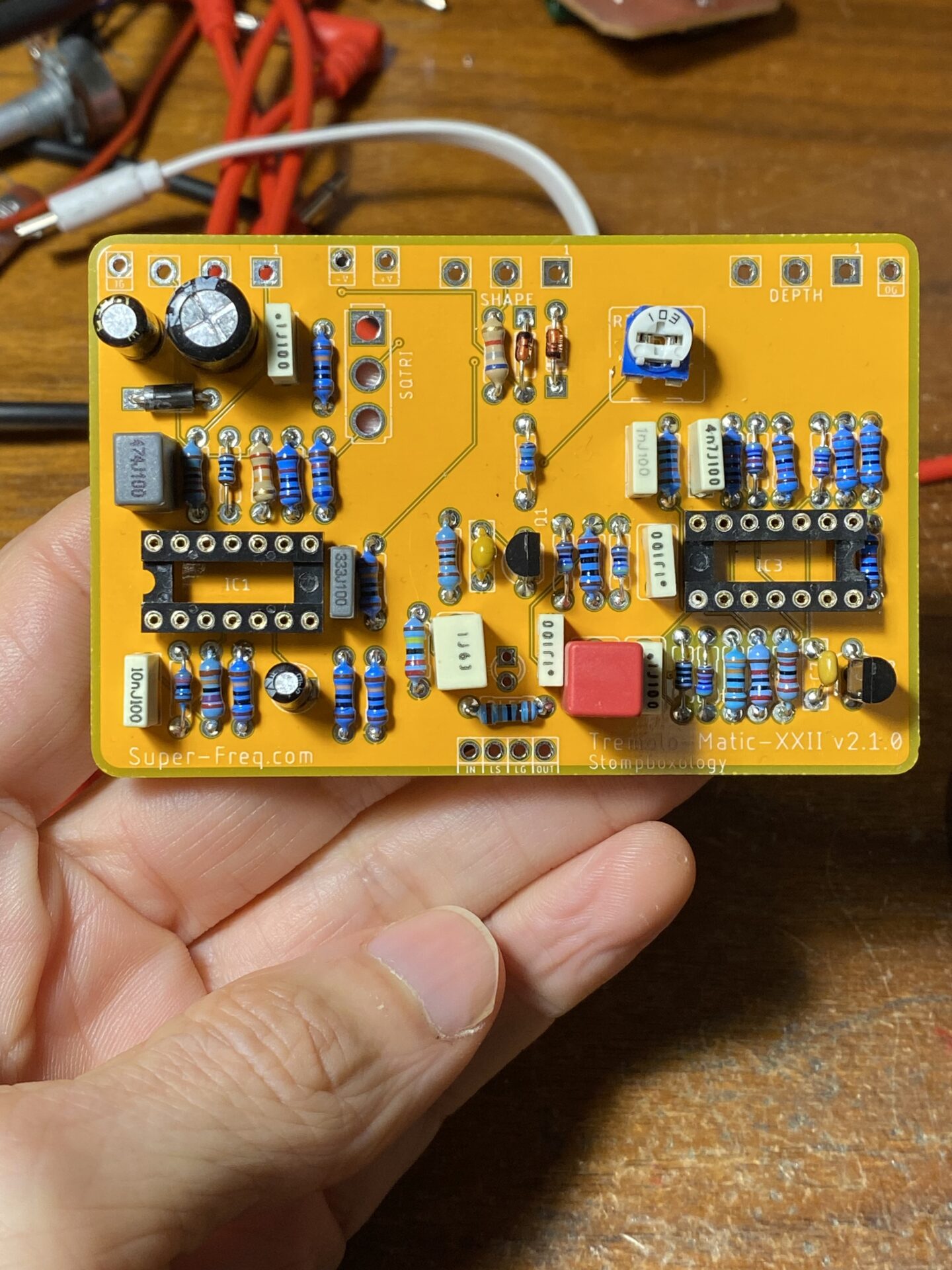
The Tremolo Matic XXII (Tremolo 22) is a great sounding tremolo. This is origianlly from Stompboxology. I’ve written more about it here. I made a few changes to the original design. This latest version adds a few improvements to the first couple revisions. I have been manufacturing these boards with PCBWay.com. They have a great price for prototyping at $5 for 10 boards 100mm. This is great for building guitar pedals.
Bill of Materials
If you plane to build this the bill of materials and schematic are below. To help out I’ve added links to parts on Tayda and Stompboxparts.com.
- [1] These were added to the original schematic. RLED is the LED current limiting resistor, use any value 1k to 10k here to determine the brightness of the LED. RPD is best practice to prevent popping when switching the effect on and off.
- [2] The LM3086 is a transistor array and is hard to get these days. The LM3046 is a replacement for the LM3086, search the internet for either of these part numbers. I found these on Amazon 5 for $7. Another alternative is to use 5 NPN transistors like 2N3094, 2N5089, or other NPN type. Which are cheap and easy to get.
Read my post about the LM3046 and LM3086 for more info.

Soldering the parts
Solder all of the parts on the list except for the SQTRI Switch, the DEPTH, RATE, SHAPE pots, and LED.
Use the two 14 pin sockets in place of the TL064 and LM3086. You’ll plug these chips into the socket when you’re done.


Drilling the enclosure
Before soldering the pots and LED drill the box. You’ll need a 1590B sized enclosure. There are some other enclosures that this might fit. The pictures below show the 1590BB sized enclosure. You’ll drill the enclosure first and fit the Switch and pots into the box then solder them in place. This ensure that the pots, switch and LED are aligned with the holes in the enclosure!
I’ll talk about drilling and the assembly process at the next pedal workshop session at Noisebridge.
I designed this PCB and had it manufactured at PCBWay.com. A few people at the Noisebridge Pedal Building work decided to build this. It should be a fun project!
The next pedal building workshop will be Saturday March 4. Sign up on meetup.
Download the drill guide print this at 100%. Check the size. Cut it out and wrap it around the box and drill.


Drill the enclosure by either marking the drill locations with a punch, through the paper guide, or just drilling through the guide.
Note! If you have a painted enclosure, drilling through paper guide will trap little metal bits between the paper and the enclosure and scratch the paint!


Assembly
Gather the LED, pots, and toggle switch. Take the nuts off of all of these. If the pots have a little that points up next to the shaft be sure to cut or break this off!
Next add the pots, LED, and switch to the board. These all go in the back of the PCB opposite the other components!
All of the pots will hang off the end of the board. A10K goes in RATE, B100K to SHAPE, and A10K DEPTH.
The LED has a longer leg and a shorter leg. The long leg goes into the square pad.
Fit the parts to the PCB without soldering. Fit it into the enclosure and add the nut and washers, flip it over solder. Doing it this way will ensure that all of the parts are square to the enclosure.
This step can be a little tricky, like playing operation and Jenga.


Wiring
You’re almost done! The last step is to fit the jacks and switch into the box and wire it all up.
Fit the jacks and wire it up as shown in the diagram below.

The 3PDT stomp switch is at the bottom notice the orientation of the lugs! It must be arranged with the flat sides facing PCB.
The jacks, at the top of the board, have two connections sleeve and tip. The sleeve goes to the ground connections on the outside of the PCB. The tips connect to the center lugs on the outside of the switch. See the next post for more info on wiring the switch.
Some 1/4″ jacks have three connections, these are stereo. If you have a stereo jack the extra connection is for the ring, you can ignore this, leave it unconnected.
At the center top is the DC jack. This is for power. There are two pins one for the barrel and one for the center. You need to connect the barrel to the positive power connection on the board +V, this is the pad that is closer to the center. The center connection of the DC jack goes to the -V pad on the PCB, this is closer to the outside of the PCB.
Some DC jacks have a third connection, this is for switching, you would use this if you had a battery.


Before adding the jacks to the box figure out which lug is the tip and which is the sleeve. For the DC power jack figure out which barrel and which is the center.
Fit the jacks into the box and put the nuts on and tighten them.


Now wire the power jack. The barrel needs to go to +V on the PCB. This is hard to read, it is the pad closer to the center of the PCB. The other connection goes to
-V on the PCB.


Leave a Reply