This is a redesign of the Tremshifter by Dead Astronaut FX. It’s a tremolo and filter in one. There are two LFOs, one driving each the tremolo and the filter, with a rate and depth control for each.
I built a couple of the Dead Astronaut boards and they worked well. I didn’t like the layout and wanted to mount the pots to the PCB for easier assembly so I redesigned the board in Eagle.
Here is the schematic:

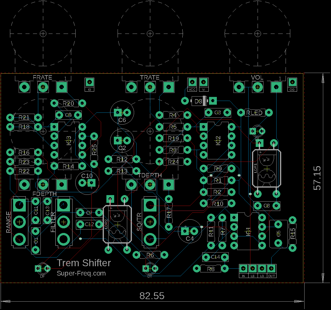
Here is an image of the PCB.

I rearranged the pots and set them up so they are all mounted to the board. I put the switches in the bottom row. The LEDs are mounted to the board in logical positions. And last, I setup the off board wiring using the standard wiring for easier off board wiring.
This layout should fit a 1590BB in portrait.
Here is a parts list:
Part Value Device Package Library Sheet
C1 1n
C2 47µ
C3 10n
C4 4µ7
C5 1µ
C6 100µ
C7 2n2
C8 330p
C9 22n
C10 10µ
C11 4n7
C12 10n
C13 22p
C14 100n
D1 LED
D3 1n5817
DF LED
DT LED
FDEPTH B100K 16MM
FILTER on/off SPDT
FRATE A1M 16MM
IC1 1458
IC2 1458
IC3 1458
LDR1 LED/LDR
R1 220K
R2 220K
R3 220K
R4 220K
R5 6K8
R6 1K
R7 220K
R8 1M
R9 1K
R10 10K
R11 470K
R12 100K
R13 100K
R14 100K
R15 100K
R16 220K
R17 3K3
R18 220K
R19 1K
R20 220K
R21 6K8
R22 1M
R23 1M
R24 1K
R25 100r
RANGE on/on SPDT
RLED 1K
SQ/TR on/on SPDT
TDEPTH B1K 16MM
TRATE A1M 16MM
VOL B22K 16MM
NOTE!
I found a mistake in the schematic here! See my build post for a fix. There needs to be a connection from IC3_A pin 3 to the junction of R16 and Pin 1 of FDEPTH pot.
To fix this on the PCB the fix is easy just run a wire from pin 3 of IC3 to right pad of R16. Turns out these are right next to each other in the layout.

Leave a Reply