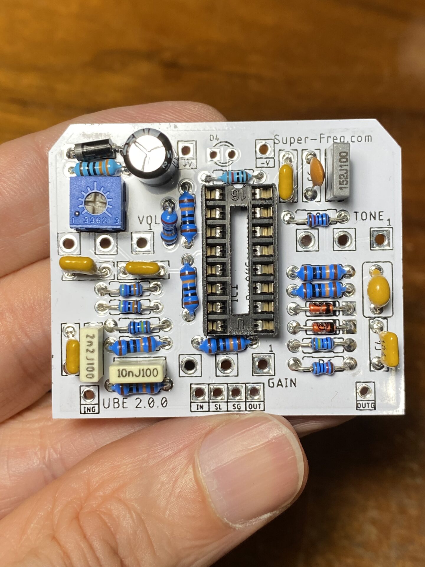
Here is an updated post for the UBE Screamer v2. The UBE Screamer was invented by the smart guys over at RunOffGroove.com, tireless purveyors of all things stomp box from the early days of the hobby.
The UBE Screamer was their entry in the FX-X contest of August 2006 over at DIYStomboxes.com. Check out that site there is so much good information there, it’s where I go for help!
This is my spin the RunOffGroove UBE Screamer. In a nutshell the UBE Screamer reenvisions the Ibanez TS-808 Tube Screamer with inverters from 4049UBE replacing the op amp stages in the original. It’s an interesting idea.
Here is the schematic from RunOffGroove.com

There is an issue here where the signal from U1A is inverted but the at U1D is not inverted. These signals are mixed at the 100k and Rx resistors into U1E. Rx is a resistor adjusted to tasted, choose values from 100k to 500k. Since the signals are out of phase, the lower the value of Rx the more the sound gets that out of phase sound that comes from picks that are out of phase.
In an attempt to solve this I used the remaining inverter stage between U1A and Rx to get the signal in phase. I also added a trim pot in place of Rx to make adjustment easier. Here is my schematic with the changes.

IC1D is the distortion overdrive path. IC1P is a x1 buffer that inverts the signal before it is mixed with the output of the overdrive/distortion section at IC1A which is the output buffer.
Here is a list of parts:
| PART | VALUE |
| C1 | 10n |
| C2 | 2n2 |
| C3 | 470n |
| C4 | 100n |
| C5 | 1n5 |
| C6 | 150p |
| C7 | 100n |
| C8 | 100n |
| C9 | 100n |
| C10 | 100u |
| C11 | 100n |
| D1 | 1n4148 |
| D2 | 1n4148 |
| D3 | 1n5817 |
| D4 | LED |
| GAIN | B500k |
| TONE | B500k |
| VOL | B100k |
| POT1 | 1M (2262 type) |
| IC1 | CD4049UBE (Must be UBE Type) |
| Socket | DIP 16 (Use a socket for IC1) |
| R1 | 1M |
| R2 | 470k |
| R3 | 470k |
| R4 | 100k |
| R5 | 100k |
| R6 | 10k |
| R7 | 1M |
| R8 | 10k |
| R9 | 100k |
| R10 | 100k |
| R11 | 100k |
| R12 | 220k |
| R14 | 330r |
| R15 | RLED (Any value 470r to 5k) |
| R16 | 100k |
| R17 | 100k |
| Enclosure | 1590B |
| Footswitch | 3PDT |


Here found a box, measured and drilled. This was left over from some experiments.


I fit the pots and LED into the PCB without soldering! Then put everything into the box and fit the nuts and washers to hold it all in place. I maneuvered the LED into its hole. Last I flipped it over, holding the PCB in place, and soldered everything.
At this stage you should be able to remove the PCB with the pots and LED as a unit, and this should fit back in the box easily. Here I drilled the DC jack, the foot switch, and the input and output jack.
Last I put fit everything back in the box to wire it all up!


Leave a Reply