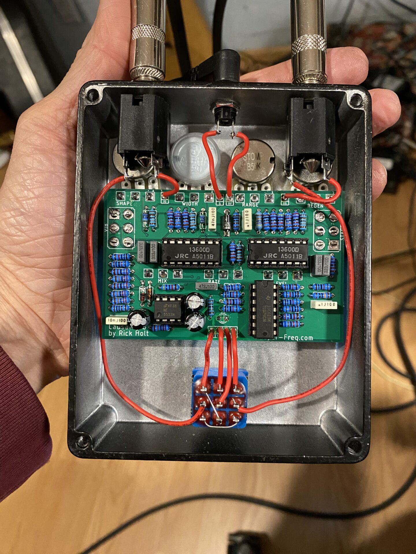
This is 4/6 stage OTA based phase shifter by Rick Holt of Frequency Central fame.
Here is a link to epic thread about this and a 4 stage design over at DIYStompboxes.com.
Here’s my build, which is working but has a couple issues that need to be worked out before it’s ready for prime time.

Design
After setting up the schematic I started designing the board. The many controls, seven pots, and two switches, needed some thought. I positioned all of the controls first taking into account the box and the jacks.
Then I added the off board wiring connections to the bottom edge of the board and ground connections for the pots along the top. I use the same wiring scheme for all of my boards. This makes wiring the same for every board which removes cognitive load, I don’t have to think about wiring!
I placed the big chips followed by the rest of the components. I made a few adjustments to get everything to fit while trying to keep related parts closer together.
Placing the controls in a place where they make the most sense from a user perspective sometimes creates problems inside the box when components then need to make connections across the PCB. Balancing the arrangement of controls with the layout of parts took some back and forth.
I used Eagle PCB and its auto-router. I’d run the auto-router take a look at the results and identify an area that needed some rearrangement, then move a couple parts around and run the auto-router again. This was a back and forth process with each iteration producing improvements.

After I got all of the traces laid in and the obvious problems solved I sent the designs to PCBWay.com for manufacture. I like this service the cost was $5 for 10 boards as long as I kept the size less than 100mm. Which is perfect for boards that fit a 1590BB enclosure in portrait. In landscape the 1590BB is a little wider than 100mm.
With 7 knobs, two toggle switches and a foot switch it needed a 1590BB box.
Using a two sided board with the smaller trace sizes made it easier to create a circuit with a high part count using through hole parts while keeping the board a reasonable size. This is an advantage of manufactured PCBs.
Build
I milled a box and marked the points to drill. Drilled everything on the drill press.


I like to fit into the PCB first, without soldering, then put everything in the box, add the nuts and washers, then solder. This keeps the pots square to the board and makes everything fit well. This works well for toggle switches which often want to sit above or below the pots.
It can be a challenge to get all of the loose parts into the box before they are soldered. With 9 controls it was impossible! So for this build I did the lower row first. This included three pots and two toggle switches. Once I got that row in and soldered, I took everything out and added the top row of four pots, put it all back in the box and soldered.
Turns out the legs on the pots were a little longer than what was shown on the footprint or my milling and drill was inaccurate. I had to bend the legs to make them fit.
Along the way I soldered the LED.


With everything in the box added the jacks and switch. Then I wired it all up. I designed this same wiring scheme I used on all of my boards which made it easy to wire from memory.
This worked right off and sounded pretty good with a range of different sounds.
This first build had a few issues that need to be worked out.
- Regen pot working in reverse, almost has too much range, there is oscillation in the last 20% of travel
- Range pot works but distorts when range is lowest. Buzzing ripping distortions the sweep reaches the peak of the cycle
- Width seems to be working
- Shape seems to be working (note: shape and width have good interaction for interesting sounds)
- Stages 4/6 works the difference is audible but not huge. I think this is correct.
- Level pot is reversed. Seems to be about unity at minimum, and way to loud at max. At the max range there’s a lot of distortion. The taper is wrong.
- Rate works but all of the range is in the last 15% of travel.
- Mix pot seems to work but range is reversed. At minimum there is no audio (for both vibe and phase.)
- Vibe switch makes a big pop when switched.


This project was not a total success. It does work and sounds pretty good at a lot of settings. There are some issues that need to be addressed before it’s ready for real use.
A few of the issues should be easy to fix. For example the gain and level pot can probably be fixed by adjusting so part values. A few things, such the reversed pots are easy fixes. A couple other issues will require some experimenting.

Leave a Reply