This project came from the Stompoxology newsletter Volume 13 Number 2 published by Nicolas Boscorelli around 2000. I can’t find a copyright date on the issue. Stompboxology was very interesting and mysterious. The Stompboxology newsletters along with the Stompbox Cookbook would be hugely popular today. But they missed the timing for their prime audience. Nicolas Boscorelli disappeared soon after and the world has not heard of him since.
Download Stompboxology here and check it out yourself: http://www.moosapotamus.net/stompboxology.html
These publications were packed with original ideas. There are no Tube Screamers and Big Muffs in these pages. The ideas are bold and original. They look well designed. I’ve built a couple of these projects and everything I have built seems to work as advertised.
This project is a tremolo built from transistors, it’s from the newsletter titled Going Discreet. It uses a VCA built from a 3086/3046 transistor array. The LFO section uses op-amps but the VCA section is built from 5 transistors contained in a 14 pin DIP.
The original Stomboxology article shows a layout for a solder less breadboard. I decided to make a PCB. I had these boards manufactured at PCBWay.com. The cost $5 for 10 boards. Which was a pretty good deal and the quality is very good.


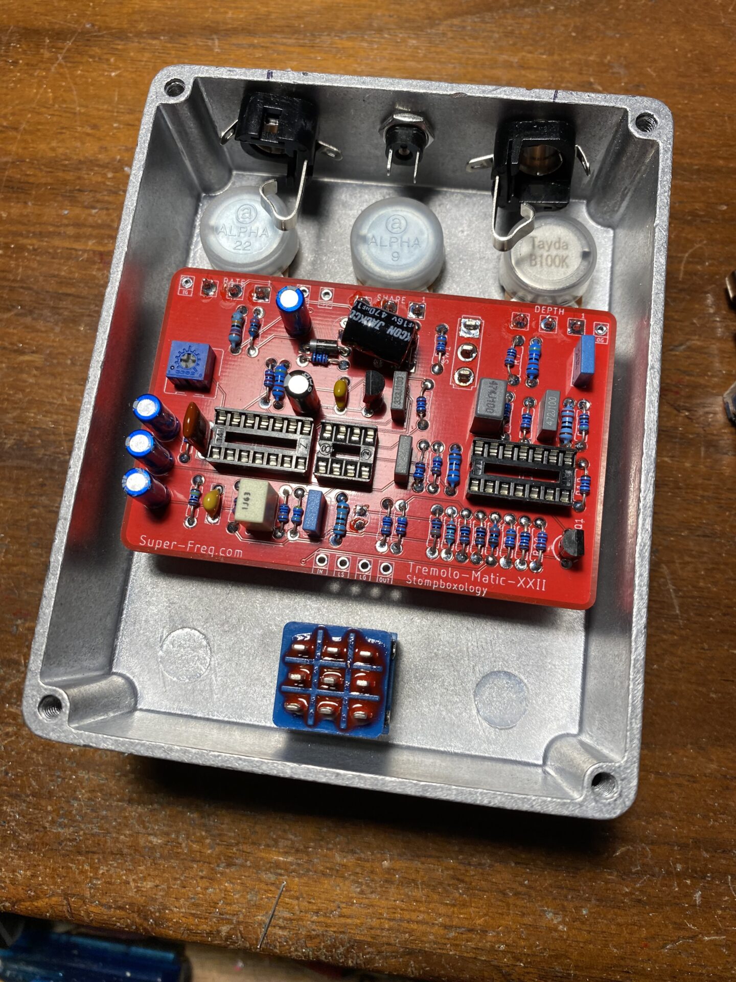
Here is the first build. Everything went together well. That big cap could use a little more room. Pots, switch, and LED worked out well.

On the first test everything worked but there was no tremolo. I had sound in bypass and I could hear some boost when effect was engaged. This meant that the signal was going through the circuit but the VCA section wasn’t doing anything.
I checked the LFO section. All of the voltages seemed to be good but the oscillator wasn’t oscillating. I posted a question and the schematic over at DIYStompboxes.com and within an hour someone pointed out that I hadn’t connected the bias voltage to the oscillator! I added a jumper between pins 3 and 7 and everything started working.


The other mistake I made was swapping the Rate and Depth markings I engraved on the enclosure. This was nothing that couldn’t be solved with the label maker!


I’m going to update my PCB design to fix the mistakes, order another test board, and then add a project page, and add this to the PCBWay share service. This should allow anyone to build this for themselves in the future.


Leave a Reply